保偏DWDM
保偏DWDM
保偏DWDM
- 产品详情
- 产品参数
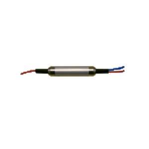
保偏DWDM
Features
Low Insertion Loss
High Quality andReliability
Applications
High Speed Networks
Coherent Deteching
Fiber Sensors
Research
Specifications
Parameters | Unit | Values | ||
Filter Type | 100GHz | 200GHz | ||
Pass Band | Center Wavelength | nm | ||
nm | 0.4 | 0.7 | ||
nm | 0.2 | 0.5 | ||
Typ. Channel Isolation at C→P | dB | 30 | 30 | |
Min. Channel Isolation at C→P | dB | 25 | 25 | |
Typ. Insertion Loss at C→P | dB | 1.0 | 1.0 | |
Max. Insertion Loss at C→P | dB | 1.2 | 0.8 | |
Reflection Band | Typ. Channel Isolation at C→R | dB | 15 | 15 |
Min. Channel Isolation at C→R | dB | 12 | 12 | |
Typ. Insertion Loss at C→R | dB | 0.3 | 0.3 | |
Max. Insertion Loss at C→R | dB | 0.5 | 0.5 | |
Typ. Extinction Ratio at 23°C | dB | 22 | 22 | |
Min. Extinction Ratio at 23°C | dB | 20 | 20 | |
Min. Return Loss | dB | 50 | 50 | |
Min. Directivity | dB | 45 | 45 | |
Center Wavelength Stability | nm/℃ | ≤0.002 | ||
Thermal Stability | dB/℃ | ≤0.005 | ||
Max. Optical Power (CW) | mW | 500 | ||
Max. Tensile Load | N | 5 | ||
Fiber Type | PM Panda Fiber | |||
Operating Temperature | ℃ | -5 to +70 | ||
Storage Temperature | ℃ | -40 to +85 | ||
*Abovespecifications are for devices without connectors.
*For devices withconnectors, IL will be 0.3dB higher, RL will be 5dB lower, and ER will be2dB lower.
*The PM fiber andconnector key are aligned to the slow axis.
Ordering information
PMDWDM-①-②②-③③③-④④④-⑤
①: Channel Spacing | ③③③: Connector Type on Port 1, 2 & 3 | ④④④: Fiber Jacket on Port 1, 2 & 3 | |||||
1 - 100 GHz | 1 - FC/UPC | B - 250um Fiber | |||||
2 - 200 GHz | 2 - FC/APC | D - 400um Fiber | |||||
3 - SC/UPC | L - 900um Loose Tube | ||||||
②②: ITU Grid | 4 - SC/APC | S - Specify | |||||
N - None | |||||||
S - Specify | ⑤: Fiber Length | ||||||
0.8 - 0.8 m | |||||||
S - Specify | |||||||